



Sanding Brush Roller Setup for Wood, Metal and Composites
A sanding brush roller gives a consistent finish only when the abrasive, contact pattern, and workpiece support are treated as one setup. The roller does not polish by pressure alone. Its flexible filaments bend against the surface, so the same abrasive can cut differently on oak, aluminum, or a carbon composite depending on how much filament contact the machine allows. The practical goal is to repeat a controlled scratch pattern, not to press harder when the finish drifts. This guide covers filament selection, roller speed, contact depth, feed, heat and dust control, and the trial checks that show whether a setting is ready for production.
What a Sanding Brush Roller Actually Controls
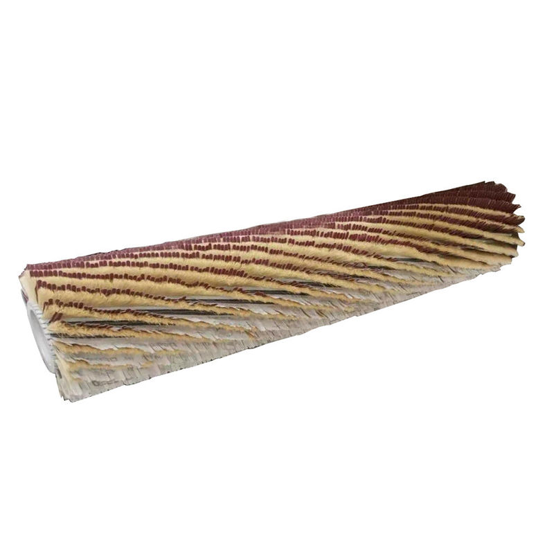
A sanding brush roller is a rotating cylinder of flexible abrasive filaments. Each filament acts like a spring: it bends against the work, recovers, and carries abrasive grit across the surface. That flexibility lets the roller follow a veneer edge, a weld toe, or a curved composite panel without the hard contact of a solid drum. It also means the cut depends on how much each filament deflects. If the roller is set too high, only the longest filaments touch. If it is pressed too deep, the filaments bend backward, heat rises, and the scratch pattern stops being uniform.
A cylindrical sanding brush is built around a controlled filament array, and the roller’s core, trim and density determine how evenly that array reaches the work. <advantage of hx cylindrical sanding brushes> covers the construction and application points behind that brush type.
The settings below matter together. Changing one without checking the others is how a trial that looked good on one coupon fails on the next part.
| Setup variable | What it changes | Useful first move | Do not infer |
|---|---|---|---|
| Filament diameter | Stiffness, contact area and edge access | Choose the smallest diameter that still holds the profile | A thicker filament does not automatically cut faster if it bridges the edge |
| Abrasive grit | Scratch depth and the stage of finish | Match grit to the defect, then step finer | A fine grit cannot remove a defect left by a coarse pass |
| Roller speed | Tip speed, cut rate and heat | Reduce speed when gloss or dark marks appear | More speed does not improve cut when the filament is loading |
| Contact depth | Filament deflection and pressure | Increase in small steps until the contact band is full width | Extra depth does not correct a crowned roller or worn filament |
| Feed rate | Dwell time and scratch overlap | Keep feed steady through the full pass | Slowing the feed does not fix an uneven contact band |

Match the Abrasive to Wood, Metal and Composites
Material choice starts with the defect and the substrate, not with a grit number. A finishing roller needs an abrasive that cuts the surface without smearing it, and a filament structure that keeps the tips open. Ask the supplier to state the grit scale it uses, because abrasive suppliers do not all label the same particle size with the same number. Two rolls that look alike can produce different scratch depths if the abrasive mineral, filament diameter, or density changes.
Abrasive nylon is a common choice for finishing rollers because the flexible backing supports the mineral and wears back as it cuts. The mineral matters. Aluminum oxide is a tough general-purpose abrasive, while silicon carbide is sharper and often used where faster cutting or a finer edge is needed. The same nylon body can behave very differently when the mineral or filament diameter changes.
Nylon filament is not a single specification, and the difference between a general cleaning brush and a sanding roller sits in the abrasive and filament structure. <main features and applications of hx nylon cylindrical brush> covers the features and applications of that cylindrical nylon brush family.
| Substrate | Filament direction | Main risk | First check |
|---|---|---|---|
| Solid wood | Aluminum oxide nylon with open tips | Resin loading and burnishing | Look for pitch on tips and glossy patches |
| Aluminum | Silicon carbide nylon; avoid steel wire | Embedded ferrous particles and smearing | Check for dark smears and rust bloom on a test coupon |
| Mild steel | Aluminum oxide nylon, or wire for heavy scale only | Heat discoloration and burr rollover | Check edge burr and surface color under raking light |
| Carbon or glass composite | Silicon carbide nylon with light contact | Fiber breakout and delamination | Inspect the cut edge with magnification |
Wood
On solid wood, the main risks are resin loading and burnishing. A dense filament and a deep contact setting can polish the surface before the profile is flat, leaving glossy patches that show under finish. A lower filament density and a light pass keep the tips open longer. On resinous woods, check the tips after every few parts and clean them before the load changes the cut. Grain direction still matters. A cross-grain pass cuts fibers that an along-grain pass would leave, so set the feed direction for the finish you need rather than the fastest route.
Metal
On aluminum and mild steel, the roller is usually doing edge blending, oxide removal, or scratch refinement. Heat is the limiting factor. A filament that rubs instead of cuts will smear aluminum and darken steel. Use a light contact setting and check the surface color under raking light. Avoid steel wire on aluminum because ferrous particles can embed in the surface and show up later as rust bloom. For heavy scale, a wire brush may be the preparation tool, but it is not a finishing roller. On stainless steel, keep carbon steel tooling away from the work if contamination control matters.
Heavy scale on steel is usually a preparation step before a finishing pass, not a job for a light finishing roller. <brushes for steel wire industries cleaning descaling derusting polishing> covers brush selection for cleaning, descaling, derusting and polishing in steel wire operations.

Composites
Composites punish excess pressure. Carbon and glass laminates can show fiber breakout, frayed edges, or delamination when the roller presses too hard or the abrasive is dull. Support the edge with a backing plate or a low-friction support so the fibers are cut rather than pushed. Use a sharp silicon carbide filament, light contact, and dust extraction at the nip. Inspect the edge with magnification after the first pass. If the white or frayed line grows on a second pass, the setup is removing fibers, not refining the edge.
Set Roller Speed, Contact Depth and Feed Together
Tip speed is pi times roller diameter times spindle speed. A larger roller at the same spindle speed produces a higher surface speed, more cuts per minute, and more heat. Changing the roller diameter is therefore a setup change, not a like-for-like swap. The same logic applies when a worn roller loses diameter: the speed at the tips falls even though the spindle readout has not moved.
Contact depth controls how much each filament bends. Start with the roller just touching the work, then increase in small steps until the contact band is full width and even. A layout dye or pencil grid on a scrap coupon makes that band visible. If the band is darker at the edges, check roller alignment and workpiece support before adding more depth. If the band is dark in the center only, the roller may be crowned or the support may be bowing.
Feed rate sets dwell time. A fast feed shortens the time each filament spends on a spot, which can leave an incomplete scratch pattern. A slow feed raises heat and can produce a dwell mark at the start or end of a pass. Program a lead-in and lead-out so the roller reaches speed before it touches the work and clears the work before it stops. On a manual table, keep the same push speed through the pass. A pause in the middle is a visible defect.
Control Heat, Loading and Dust Before Finish Drifts
Heat is the first sign that the setup is asking too much from the filament. A dull or loaded tip rubs instead of cutting, so friction rises and the surface can gloss, darken, or smear. Wood resin and metal particles both reduce the available cutting edge. Check the filament tips with a raking light after the first few parts. If the tips are glazed or packed, clean them or change the roller before the finish changes.
Extraction should capture dust at the nip, not at the far end of the hood. Dust that escapes the hood can settle on the work and be pressed back into the surface on the return pass. A strip brush seal on the hood edge closes the gap without blocking the workpiece. The seal needs to touch the work, but not so hard that it lifts the part or adds drag.
For composites, capture dust at the source and avoid dry sweeping that puts fibers back into the air. For metal, keep the work and the roller free of loose scale. A particle caught between the filament and the surface can leave a deep scratch that looks like a grit fault.
Run a Trial Before the Production Lot
-
Record the baseline. Write down the substrate batch, thickness, grain direction, filament type, grit scale, roller diameter, spindle speed, feed setting, contact indicator, extraction setting, and ambient conditions. A result without these details cannot be repeated or compared.
-
Map the contact band. Mark a scrap coupon with layout dye or pencil lines. Run one short pass at a light depth. Inspect the full width. A band that is full width and even is ready for the next step. A band that is narrow, crowned, or patchy points to alignment, roller condition, or support before it points to abrasive.
-
Build a finish ladder. Run successive short passes with small increases in contact depth. Keep each coupon and label it with the setting. Stop at the first pass that removes the defect without adding a new scratch pattern. Do not skip from a coarse cut to a finish pass on the production part. The jump hides the step where the finish changed.
-
Check edges and heat. Inspect edges under raking light. On composites, use magnification and look for fiber breakout. On metal, look for smears, color change, and burr rollover. On wood, look for gloss, raised grain, and resin on the tips. Let the part cool before you judge the finish. A warm surface can look different after it settles.
Keep the accepted coupon and the setting sheet at the machine. A brush table or a low-friction support that keeps the part flat is part of that setup, because a part that rocks changes contact depth without any change to the roller.

If the part cannot be supported flat, reduce depth and use a fixture that follows the contour. Do not rely on the roller to flatten a warped panel.
Common Finishing Faults and the First Check
Most finishing faults come from one of three places: contact depth, roller condition, or workpiece support. Work through those before changing the abrasive. A grit change can hide a mechanical problem for a few parts, then the fault returns.
| Symptom | Likely cause | First check |
|---|---|---|
| Glossy or burnished patches | Too much contact depth, speed too high, or loaded filament | Stop the pass, inspect the tips, and reduce depth before changing grit |
| Uneven cut across the width | Crowned roller, worn filament, or uneven support | Mark a scrap coupon and check the full contact band |
| Swirl or comet tail marks | Feed too fast, roller misalignment, or vibration | Check roller runout and keep feed steady |
| Fiber breakout on composites | Dull abrasive, too much depth, or unsupported edge | Support the edge and try a lighter pass with fresh filament |
| Metal smear or discoloration | Heat from dwell or a filament too fine for the oxide | Reduce speed and confirm the abrasive is suited to the metal |
If a fault appears only at the start or end of a pass, the roller is dwelling while the feed accelerates or decelerates. Add a lead-in and lead-out, or start the pass before the work enters the contact zone. If the fault follows the same lane across different parts, check roller runout and support, not the abrasive. If it appears only on the second side of a panel, check whether the first pass changed the part thickness or left dust on the support.
For a local edge repair or a flat area that the roller cannot reach, a disc brush can be the right hand tool. Keep it as a repair step, not a substitute for a roller setup that is cutting unevenly.

Send Your Surface Finishing Requirements
A trial coupon is the fastest way to separate a filament problem from a machine problem. Send the substrate, part size, target finish, current abrasive and grit scale, roller diameter, spindle speed, feed setting, extraction setup, and a photo of the surface fault to [email protected] or call +86 1580 0932 713. Huixi Brush can review the details against your sample and discuss a trial roller specification.
FAQ
What grit should I start with on a new sanding brush roller?
Start with the finest abrasive that removes the defect in a short, controlled pass, then step coarser only if the cut is too slow. There is no universal starting grit because the same number can mean a different particle size on another supplier’s scale. Run the first pass on a scrap coupon that matches the production substrate, and record the grit scale, filament diameter, speed, and depth. If the surface glosses before the defect clears, the abrasive is too fine or the contact depth is too high.
Can one sanding brush roller finish wood, metal and composites?
A single roller can be used across those materials only within a narrow range of settings, and usually with a change in abrasive or contact depth. Wood needs open filament tips to limit resin loading. Aluminum needs a nonferrous approach to avoid embedded iron. Composites need light contact and sharp abrasive to limit fiber breakout. A roller that works on oak will not necessarily leave an acceptable edge on a carbon laminate. Match the roller and the setup to the substrate, then prove it on a coupon.
How can I tell if contact depth is too high?
Look for three signs: a contact band that is wider than the work, glossy or dark patches, and filament tips that stay bent after the pass. A high depth also raises heat and can round an edge that should stay sharp. Reduce depth in small steps and rerun the coupon. If the band is still uneven at light depth, check roller alignment, roller runout, and workpiece support before changing the abrasive.
Why does the finish change after a few hours of running?
Check wear and loading before you change the recipe. Filament tips can glaze, pack with resin or metal, or wear shorter, and all three change the cut. Heat build-up in the fixture and extraction duct can also change the surface over a long run. Compare a new coupon with a part from the current run, then inspect the roller under raking light. If the contact band has narrowed, the roller or support has moved. If the band is even but the surface is glossier, the tips are dull or loaded.
If you’re interested, check out these related articles:
abrasive disc brush an efficient tool for many applications
abrasive disc brush an excellent industrial surface treatment tool


 Whatsapp
 Email